What is a Variable Frequency Drive?
Updated on October 1st 2025
A variable frequency drive (VFD) is a type of motor controller that can adjust the speed of an AC electric motor. It does this by varying the frequency and voltage supplied to the motor. A variable frequency drive is often called an adjustable speed drive (ASD), variable speed drive (VSD), adjustable frequency drive (AFD), AC drive, inverter, or just simply a drive. Some of the simpler terms have other connotations throughout the electrical industry, so it’s usually referred to as a VFD or ASD in technical environments.
A VFD works by adjusting the frequency of the alternating current (AC) waveform a VFD sees. For example, North American systems are typically 60Hz systems, meaning there are 60 cycles (positive and negative waveforms) per second. The electricity creates an electromagnet in a motor and the polarity changes in a cycle (positive and negative) rotate the shaft of the motor.
This construction means that the way to adjust the speed of AC motors is to send a different frequency to the motor, changing how quickly the shaft is spun. Thus, "VFD" is the most common term because the device varies the frequency that the motor is driven.
How does a Variable Frequency Drive work?
Although VFD technology continues to advance daily, most VFDs have the same general topology, comprised of three distinct sections.
The Converter Section of a VFD
First is the converter. This is the section that takes your incoming AC sine wave and converts it to direct current (DC). It does this with diodes. When the voltage is high enough, the diode opens and allows current to flow. It can help to picture this like a plumbing system with check valves where the voltage is your water pressure forcing the valve open.
In a standard low voltage VFD, meaning under 1000V, there are six diodes. Each phase has one on the positive side of the bus and one on the negative, and most systems have three phases – to see how this differs on single phase systems, check out our article called: Can a VFD Convert Single-Phase Power to Three-Phase?
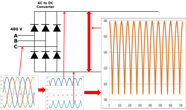
The picture below gives a demonstration of how this works. When the A-phase voltage is more positive than B- or C-phase voltage, that diode opens. When B-phase becomes more positive than A-phase, that diode will open and the A-phase diode closes. This same thing happens on the negative side. This means that we get six current “pulses” as each diode opens and closes. This called a “six-pulse VFD.”

The converter section of a variable frequency drive
The DC Bus Section of a VFD
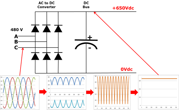
Let's dig into the details a little deeper. This depicts a 480V power syste, where the 480V rating is "rms" or root-mean-squared. The peaks on this 480V system are 679V. As the diodes open and pull in the peaks, this power goes to the second main component, the DC bus. This bus is seeing the DC voltage with an AC ripple, as shown in the picture above, running between 580V and 680V. We can get rid of the AC ripple by adding a capacitor, as shown in the picture below.

The converter and DC bus sections of a variable frequency drive
A capacitor operates in a similar fashion to a reservoir or accumulator in a plumbing system. It absorbs the AC ripple and delivers a smooth DC voltage. The DC bus now sits roughly in the 650V range, and the ripple magnitude is reduced. The actual voltage will depend on the voltage level of the AC line feeding the drive, the level of voltage unbalance on the power system, the motor load, the impedance of the power system, and other devices like reactors or harmonic filters on the drive.
The Inverter Section of a VFD
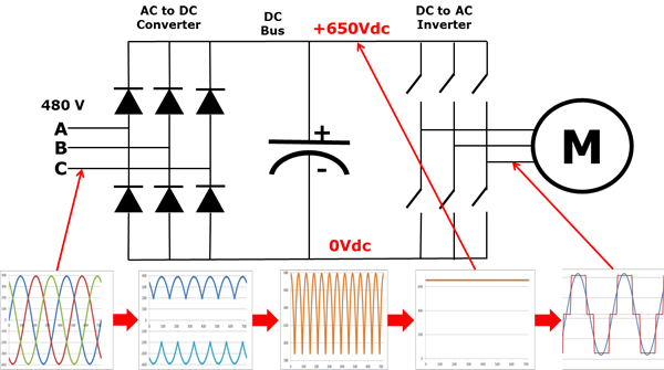
The third section of the VFD is the inverter. This is a section that converts DC back to AC and is called an inverter to distinguish it from the front-end diode converter. It’s become common in the industry to refer to any DC-to-AC converter as an inverter. This has become especially common in the solar industry as PV panels produce DC that needs to be converted to AC for use on the grid.

The inverter section added to the variable frequency drive diagram. Note that in a real VFD, the switches shown would actually be transistors.
The inverter functions by switching transistors on and off at different rates to simulate an AC sine wave. These transistors are typically called IGBTs, or insulated-gate bipolor transistors. Just like there are diodes on each phase for both positive and negative on the front end section, there are transistors on both sides of each phase on the inverter. The posistive switches are connected to the positive DC bus, with the other switches connected to the negative DC bus. By changing which switches are closed, the VFD can make any phase on the motor become positive or negative at will, generating any frequency.
Pulse Width Modulation (PWM)
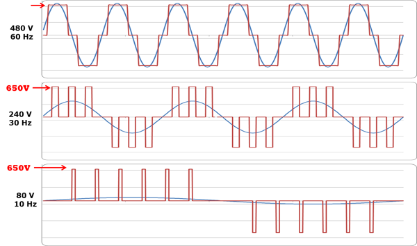
This simulated sine wave of pulses, all at about 650V, create a “rectangular” or “square” waveform instead of a true sinusoidal output. This is called pulse width modulation, or PWM. The PWM waveform works fine for motors but isn’t a good choice for a general purpose distribution system.

A simplified depiction of a PWM waveform generating different frequencies. The blue sine wave is shown for comparison purposes only as the drive does not generate a true sine wave.
Just like the picture above shows, if we want to change the motor to running at 30Hz, the motor runs slower. In order to maintain the V/Hz ratio, the voltage is also reduced to 240V (see the VFD Motor Theory article for more on this). PWM allows us to adjust the voltage by changing the amount of time the voltage is "on". If we want the average voltage to be 240V instead of 480V, it would be off half the time to achieve this result, similar to the picture above. The more you slow it down, the farther spaced the pulses are to maintain the V/Hz ratio.
What's Changing in VFDs?
The topology above has remained consistent for decades for most major low voltage drives, but there are changes currently hitting the industry. One example of a change is the introduction of Silicon Carbide, or SiC, as a construction material. This allows for faster switching, less heat, higher efficiency, and more control.
In VFDs, this is introduced in SiC MOSFETs, or metal-oxide-semiconductor field-effect transistors. These devices can replace transistors, but also can replace diodes on the front end, solving issues like harmonic distortion that we’ll talk about later. You can learn more about these advances in an article we wrote about one of the companies leading these changes, SmartD.
There’s also changes in how drives are packaged. Even if the topology doesn’t change, manufacturers might integrate bypass, power quality filters, or other components into the same VFD chassis. They may also have higher enclosure protection levels to make it more guarded from contamination.
One other shift we’ve seen is in controls. Many drives now include ethernet-style communications as the standard to match facilities that are upgrading their building management systems.
Why Use a VFD?
Why does anyone use a VFD? VFDs have several benefits, with the major ones being process control, energy efficiency, and the ability to extend equipment life. There are some other minor benefits as well, such as improving power factor and converting from single to three phase.
Using VFDs for Process Control
The main reason to use a variable frequency drive is to control the speed of a process. An easy way to visualize this is with a water system for a city. Historically you had two options to adjust the flow of water:
- Switch between having your pumps running at full speed or not running at all
- Using mechanical controls like valves to adjust flow rates
These have major drawbacks, including the mechanical stress you’re putting on a system to hold the flow back. Using a VFD means rather than pumping at 100% and finding ways to hold the flow back, you can simply pump less water when it’s not needed.
The same benefit applies to all the common VFD applications. Conveyor belt speeds can be adjusted based on the load, crushers can slow down for large objects, fans can change speed based on ambient temperature.
Using VFDs for Energy Savings
When you slow the speed of the motor down based on your application needs, you don’t just save mechanical stress, you also can save on energy. When your motor runs at half speed, you use less electricity and can save money.
For some applications like fans and centrifugal pumps, it’s even better. These applications are subject to affinity laws, which mean that the reduction in speed isn’t a linear relationship to energy use. In these cases the relationship is cubic, meaning that if you cut a fans speed to 50% of its original speed, you would generate only 25% of the pressure and use only 12.5% of the power.
In the water system example above, not only have you now reduced the need to put stress on valves and pipes, but you’ve reduced your electric utility bill and your effect on the environment.
Using VFDs to Extend Equipment Life
These same benefits mean that in many cases, you can extend the life of your equipment. Motors, pumps, fans, and other equipment don’t have to run as hard. Pipes hold less pressure and valves don’t hold back flow. The hours of runtime on your equipment is easier so it can last longer.
You also reduce the inrush that your motor sees. Motors can consume over 600% of their rated current on startup, but with a VFD that inrush is gone. That means you don’t get that sledgehammer of electricity hitting your motor every time you start it.
Inrush isn’t just a problem for your motor, it may be a problem for your utility. If you might need 600% of the rated power to start, they have to be able to supply that, which means you might pay for more electricity than you need.
Other Benefits of Using a VFD
Low power factor is another issue that becomes more common as the grid has more stress. You can learn more by reading the "What is Power Factor, and Why Does It Matter?" article. It is important to know that standard induction motors have worse power factor than a VFD. Rather than deal with a power factor somewhere in the 65% - 85% range, you can easily bring your system's power factor rating up to about 96% with almost all VFDs.
Phase conversion is another fringe benefit of a VFD. Using VFDs for phase conversion can be complicated, but you can learn more about it in our article about VFDs and Phase Conversion. The easy recommendation here is that you might be able to simplify your system by using your VFD as a phase converter if you need to control the speed of the motor. If you don’t need to control the speed of your motor, you should look into phase converters as a VFD is probably over-engineered for your situation.
Are There Drawbacks to Using a VFD?
Are there any downsides to adding a variable frequency drive to a motor system? VFDs produce some issues that can affect your power quality – like harmonics – or else damage components of your motor – like dV/dt and bearing currents. All of these issues can be overcome, but you should plan for them when implementing a VFD.
For harmonic distortion, you should look at either a VFD topology that produces less harmonics or at adding harmonic filters to your VFD. These can be incorporated into either the VFD chassis or a VFD panel and can even be retrofitted after the fact.
For dV/dt and reflective wave phenomenon, you may see issues when you have long cable lengths (100 feet and above) from your VFD to your motor, or have cables that are submerged. These can typically be mitigated with an output filter on the VFD.
For bearing currents, there are multiple ways to solve the issue. You can upgrade to insulated bearings or go with a more cost-effective option like a shaft grounding ring, or SGR.
Get Help with Your VFD
Variable frequency drives can be unusual for many facilities or contractors to encounter, but we deal with them every day, There are many consideratoins based on how they work, and the VFDs.com team knows all the ins and outs. Reach out to our team on your next VFD project so we can make sure that you avoid costly mistakes and get the right VFD for your system.
